Texel TapeMetrix: User Manual
Overview
Texel TapeMetrix is a software designed to automate digital body measurement based on 3D models. The software features compatibility with Texel Portal proprietary 3D scanners as well as third-party solutions, such as handheld 3D scanners, photogrammetry systems, and mobile devices. TapeMetrix automatically generates approximately 100 baseline parameters (including circumferences, heights, and distances) according to GOST and ISO standards. Users retain the ability to modify the resulting measurements or add custom parameters manually via an intuitive user interface. Data processing and storage are fully localized (no internet access required), thereby ensuring total data privacy and security.
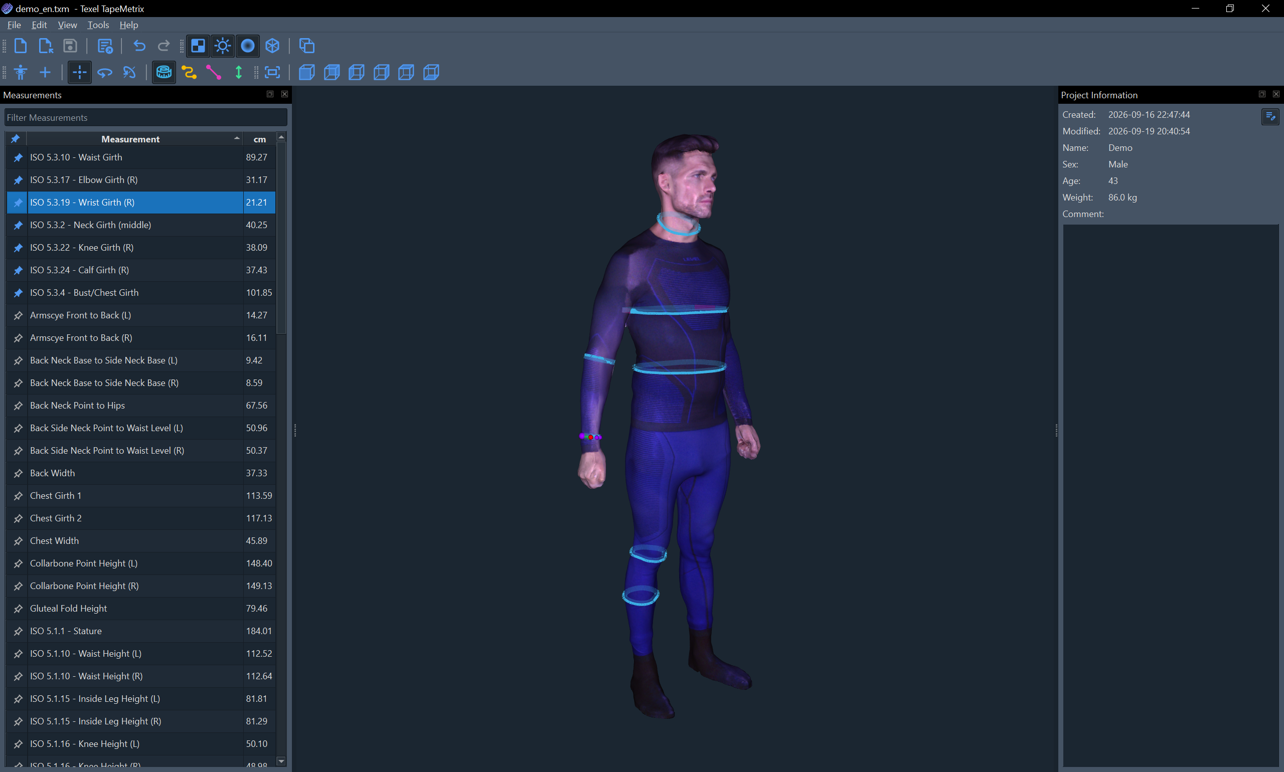
This manual describes the core functionality of Texel TapeMetrix and the key aspects for using this software effectively. The manual contains information regarding the current version of Texel TapeMetrix and is updated as new versions are released and functionality is expanded.
Key Concepts
-
3D Model (or Polygonal Model) is a classic representation of 3D data in computer graphics in the form of a polygonal mesh - a set of points connected by polygons (usually triangles). This representation is standard for applications in the field of 3D graphics and modeling. Popular file formats for storing 3D models include OBJ, PLY, STL, FBX, glTF, and others. Texel TapeMetrix supports importing of a wide range of formats, ensuring compatibility with third-party software.
-
Project is a way of storing a 3D body model, measurements, and additional information. Texel TapeMetrix projects have the ".txm" file extension and can be saved to disk, loaded from disk, and sent via email or other communication channels. Files with the ".txm" extension are guaranteed to open with a newer version of Texel TapeMetrix (backward compatibility); forward compatibility is generally maintained but not guaranteed.
-
Keypoint is a point on the surface of the 3D body model through which a measurement must pass. In Texel TapeMetrix, keypoints can be created (automatically or manually), deleted, and moved. Keypoints are connected by one of four types of paths, each having its own color-coding both when visualized on the model and in the toolbar icons.
-
Path is a way of connecting two keypoints. Texel TapeMetrix supports 4 types of paths:
- Tape models the behavior of a tailor's measuring tape passing over hollows on the body surface (for example, when measuring a bust girth).
- Contour connects points by taking the shortest path strictly along the body surface (geodesic path). It is used for contoured measurements.
- Distance connects points with a straight line and can pass through the 3D model.
- Height measures the height (vertical distance) between two keypoints.
-
Measurement is a list of keypoints connected by paths. A single measurement can contain different types of paths and can be either closed (e.g., waist girth) or open (e.g., chest width). The numerical value of a measurement is calculated from the combined lengths of its constituent paths, with support for various length units.
User Interface
The main window of Texel TapeMetrix consists of the following elements:
-
Menu bar, containing the File, Edit, View, Tools, and Help top menu items. All application features are accessible from the menu, with the most frequently used actions bound to keyboard shorcuts.
-
Toolbars, containing icon buttons for the most frequently used functions. Toolbars can be hidden or moved to any convenient place within the window.
-
Side panels containing the core functionality (Measurements and Project Information). These panels are designed as dock widgets, meaning they can be positioned anywhere within the main window or detached from it entirely. If desired, unused panels can be hidden (their visibility is controlled via the View menu). To restore the window layout to its default state, use the View > Reset window layout menu item.
-
Central area of the window serves as a viewport to display 3D model and perform actions on measurements (for example, adding or deleting keypoints).
You can change the interface language and theme in the Settings (File > Settings...).
Creating a New Project
To create a new project, click the New Project... button on the start screen, or click the File > New... menu item (or the corresponding button on the main toolbar). You can also use the Ctrl+N keyboard shortcut.
When creating a new project, the open file dialog will be displayed in order to select a 3D model for import. The basic requirements for the 3D models to be successfully loaded and processed are listed below:
- Supported file formats: OBJ, GLB, glTF, COLLADA (DAE), FBX, X3D, STL, 3MF, PLY
- The model can be without color or with a texture (in JPEG or PNG format)
- Recommended triangle count: 50,000 to 150,000
- Supported model units: millimeters, centimeters, meters, inches, feet (automatic detection is supported)
- Upward axis: Y or Z (automatic detection is supported)
- For automatic measurements to work properly, the 3D model must be in the A-pose (feet shoulder-width apart, arms positioned symmetrically at a 30-45 degree angle from the body) and wearing form-fitting clothing (or underwear)
- The model may contain small geometry artifacts typical of 3D scanning; however, in case of severe topology issues, the model import may fail
After selecting the file and successfully loading the 3D model, the following dialog will be displayed:
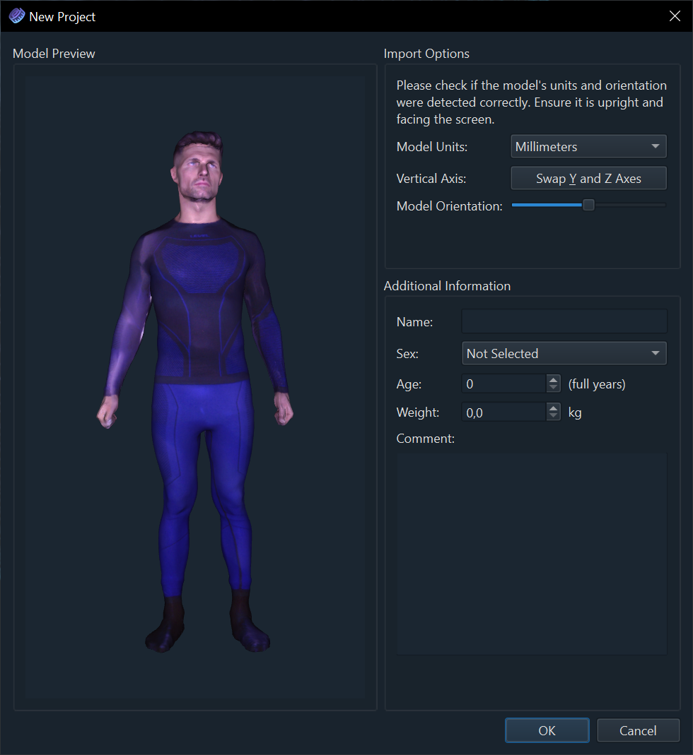
Model units and orientation are determined automatically; however, if they are detected incorrectly, you can make the necessary changes. You can also provide additional project information at this stage. It is recommended to immediately specify the sex of the person (Male or Female). To continue, click the OK button at the bottom of the dialog.
Adding Automatic Body Measurements
After successfully creating a new project based on the selected 3D model, you will be prompted to add automatic measurements to the project as a starting point (you can also add additional automatic measurements at any time):
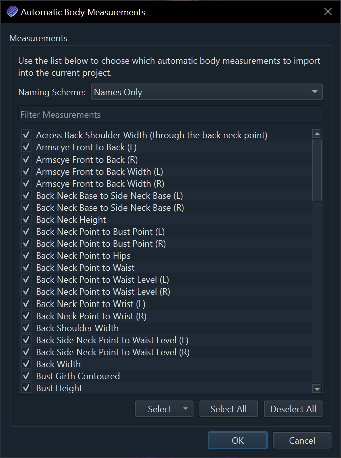
Select the desired measurements from the list of supported options (check the corresponding checkboxes). Use the Filter Measurements field located right above the list for quick search. For quick selection, use the buttons below the list: Select (allows choosing frequently used measurement sets), Select All, and Deselect All.
The Naming Scheme drop-down list allows you to set the naming scheme: Names Only, identifiers according to the ISO 8559-1 standard, or identifiers according to the GOST 31396 / 31399 standards.
After selecting the desired automatic measurements, click the OK button at the bottom of the dialog. If you do not need to add automatic measurements, click the Cancel button. You can add automatic measurements at any time via the Tools > Automatic Measurements... menu item, or by clicking the corresponding button on the toolbar. You can also use the Ctrl+M keyboard shortcut.
Managing Measurements
The Measurements panel (located on the left side of the window by default) is used to view and manage measurements; it contains a table listing all the body measurements in the current project. If the panel is not displayed, you can enable its visibility using the View > Measurements checkbox (or the Ctrl+Shift+M keyboard shortcut).
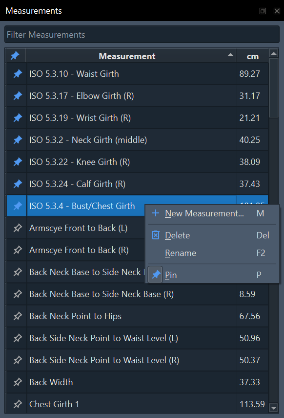
To quickly find measurements, use the Filter Measurements field above the table. Clicking on the table column headers changes the sorting order, while clicking on the icon in the left column pins the measurement to the top of the table (it will also always be displayed on the 3D model, even if another measurement is active).
Left-clicking on a measurement name selects it (makes it active) and switches it to editing mode (you can move keypoints, or add and delete them). To rename a measurement, double-click on its name, or select it and press the F2 key. To delete the selected measurement, press the Del key. All actions are also available from the context menu, which can be opened by right-clicking on the desired measurement.
3D Navigation and Display Control
While working with measurements on the 3D model, you can rotate, zoom, and pan the virtual camera:
-
Move the mouse while holding down the left mouse button to rotate. If you are using a laptop touchpad, move your finger across the touchpad while pressing down on it.
-
Use the mouse wheel to zoom in or out. On a touchpad, you can use the pinch gesture (touch the touchpad with your thumb and index finger and spread them apart to zoom in, or pinch them together to zoom out).
-
Move the mouse while holding down the mouse wheel (middle mouse button) to pan the virtual camera. On a laptop touchpad, you can move your finger across the touchpad while pressing down on it while holding the Shift key with your other hand.
-
To reset the virtual camera position, you can use the Reset Camera button on the toolbar, the View > Reset Camera menu item, or press the Home key on your keyboard.
-
To quickly switch between different views, use the corresponding buttons on the toolbar, the items in the View menu, or the keyboard shortcuts (1 through 6).
For convenience, various 3D model display modes are also provided:
-
The Show Texture button on the toolbar (or the View > Show Texture menu item, the X hotkey) enables or disables the display of the 3D model's texture.
-
The Enable Lighting button on the toolbar (or the View > Enable Lighting menu item, the L hotkey) lets you to turn the light source on or off.
-
The Smooth Shading button on the toolbar (or the View > Smooth Shading menu item, the S hotkey) switches between shading modes (smooth or flat/faceted).
-
The Wireframe button on the toolbar (or the View > Wireframe menu item, the W hotkey) enables the wireframe display.
-
The Orthographic Projection button on the toolbar (or the View > Orthographic Projection menu item, the O hotkey) switches between perspective and orthographic projections. Orthographic projection is a method of representing three-dimensional objects on a plane where the projection lines are strictly perpendicular to the projection plane. The main advantage of orthographic projection is the complete absence of perspective distortion, which allows maintaining the exact proportions and dimensions of the object.
Creating a New Measurement
To create a new measurement, use the New Measurement button on the toolbar (or the Tools > New Measurement menu item, the M hotkey). After entering the name for the new measurement, press the Enter key.
Texel TapeMetrix supports several tools for defining measurement geometry:
Defining a Measurement Using Keypoints
Select the Keypoint tool on the toolbar (or the Tools > Keypoint, the K hotkey) and left-click anywhere on the surface of the 3D model - this will create the first keypoint of the measurement. Then click on another spot on the surface of the 3D model and this will create a second keypoint, connected to the first one by the currently selected path (set on the toolbar or via the Tools menu). Paths of different types are indicated by their corresponding colors in the icons, cursors, and on the 3D model itself:
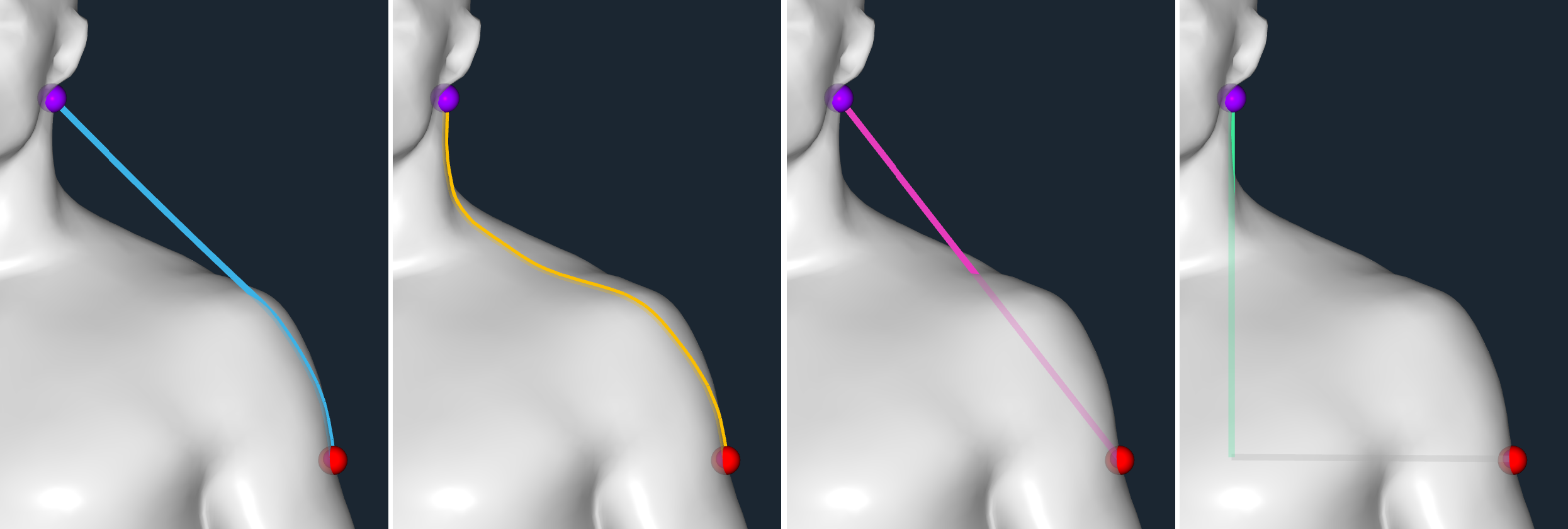
- Tape (Tools > Tape, the T hotkey) models the behavior of a tailor's measuring tape passing over hollows on the body surface (for example, when measuring a bust girth).
- Contour (Tools > Contour, the С hotkey) connects points by taking the shortest path strictly along the body surface (geodesic path). It is used for contoured measurements.
- Distance (Tools > Distance, the D hotkey) connects points with a straight line and can pass through the 3D model.
- Height (Tools > Height, the H hotkey) measures the height (vertical distance) between two keypoints.
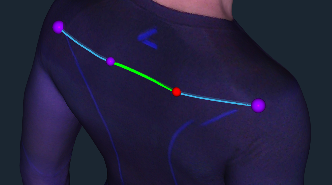
Keypoints are represented by purple spheres, the active point is highlighted in red, and the active path (from the previous point to the selected one) is shown in green. The starting and ending points of the measurement are marked with slightly larger spheres. To select an active point, left-click on it; to adjust its position, drag it with the mouse to a new location. To delete the selected point, press the Del key or choose the Delete Keypoint option from the context menu, which is accessible by right-clicking:
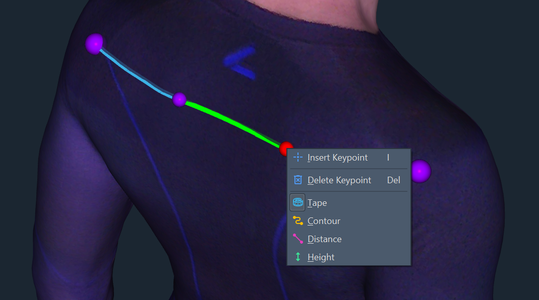
In addition, the context menu allows you to add a new keypoint between the active and previous keypoints (the I hotkey) and to change the type of path between the keypoints.
To create a closed measurement (for example, a girth), move the end keypoint close to the starting keypoint (or immediately create a new keypoint near the starting one) to snap them together automatically.
Creating a Horizontal Girth
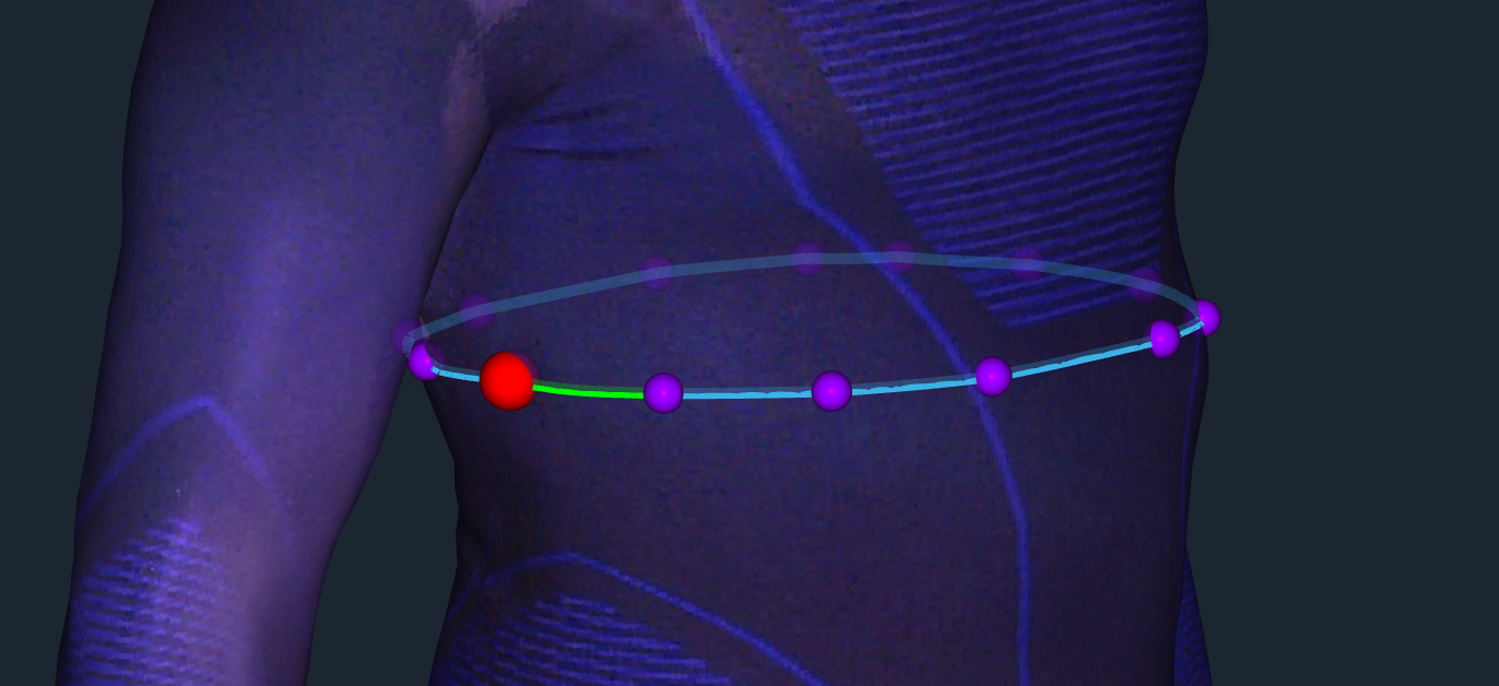
To quickly create a horizontal girth (strictly parallel to the floor plane), select the Horizontal Girth tool on the toolbar (or the Tools > Horizontal Girth menu item, the G hotkey), and then click anywhere on the surface of the 3D model. As a result, a horizontal girth passing through the specified surface point will be automatically constructed:
Creating a Limb Girth
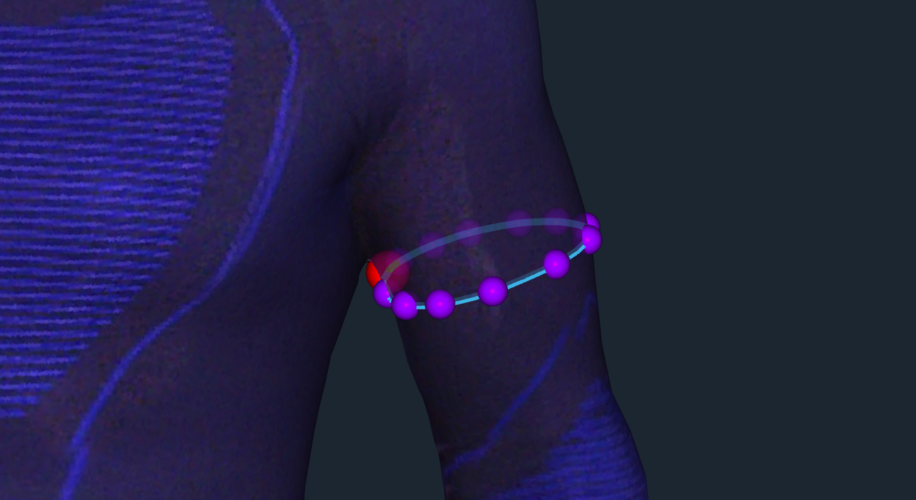
In some cases, the measurement plane needs to run perpendicular to the body axis (for example, when creating measurements for arms or legs). To create such a measurement automatically, select the Limb Girth tool on the toolbar (or the Tools > Limb Girth menu item, the B hotkey), and then click anywhere on the surface of the 3D model. A girth path oriented perpendicular to the local axis will be automatically constructed through the specified surface point:
Managing Projects
While working on a project, every action (for example, deleting a measurement, changing keypoints, etc.) can be undone if it was made by mistake. To undo the previous action, use the Undo button on the toolbar, the Edit > Undo menu item, or the Ctrl+Z keyboard shortcut. To redo an undone action, use the Redo button on the toolbar, the Edit > Redo menu item, or the Ctrl+Y keyboard shortcut.
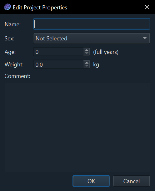
Texel TapeMetrix uses its own proprietary project file format - files with the ".txm" extension that contain the 3D body model and all created measurements, as well as additional information (for example, the person's sex, age, weight, name, and optional comments). Additional information can be modified by selecting the File > Project Properties... menu item, or by using the button on the Project Information panel:
You can open a project by double-clicking on it in your file manager, or by clicking the Open button on the toolbar (or select the File > Open... menu item, or use the Ctrl+O keyboard shortcut). To save a project to disk, use the Save button on the toolbar (or select the File > Save menu item, or use the Ctrl+S keyboard shortcut). To save the project to a new file, use the Save As... button or the corresponding menu item.
Files with the ".txm" extension are guaranteed to open with a newer version of Texel TapeMetrix (backward compatibility); forward compatibility is generally maintained but not guaranteed. In addition to being stored on disk, project files can be used to share information (for example, via email), provided that the recipient also has the Texel TapeMetrix software installed.
Data Export
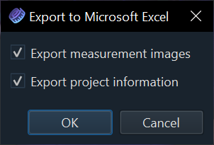
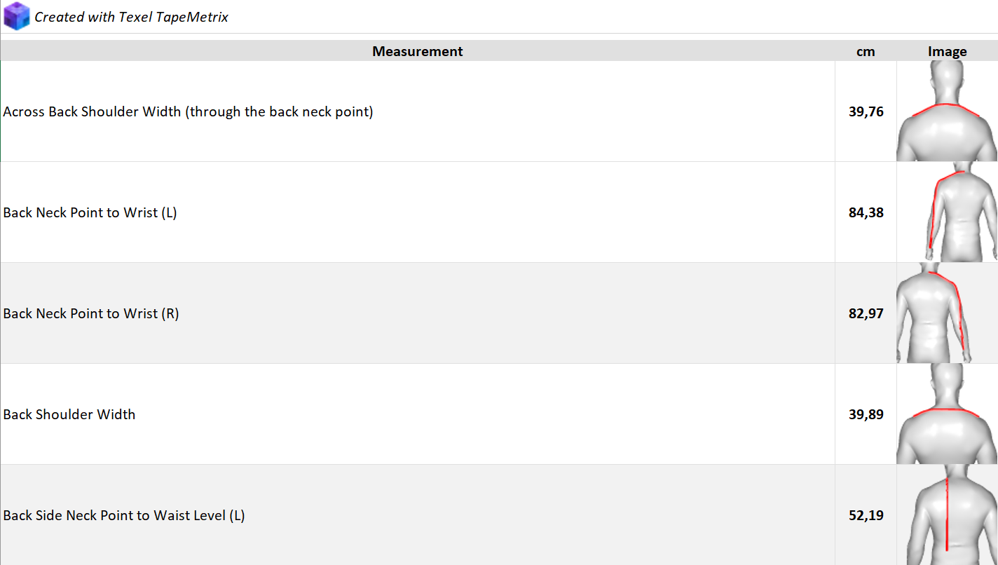
Texel TapeMetrix supports exporting measurements to Microsoft Excel (XLSX) and CSV formats. Additionally, exporting to Microsoft Excel provides extra features, such as visualization of each measurement (image generation) and exporting project information onto a separate sheet. Due to format limitations, only the measurements themselves (names and values) are exported to CSV.
To export data, use the Export button on the toolbar (or select the File > Export... menu item, or use the Ctrl+E keyboard shortcut). When selecting the Microsoft Excel format, an additional export options dialog will be shown:
After clicking the OK button, a Microsoft Excel file will be created with the selected options:
Changing Settings
Use the File > Settings... menu item to change the application settings, such as the user interface language and theme, as well as the units of measurement and weight:
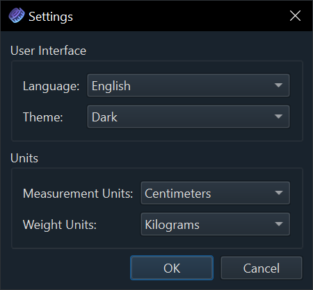
To save the selected settings, click the OK button at the bottom of the dialog.